Smart Embedded Systems for    
Industrial, Commercial and Educational Applications
   Home | Products  |  Download | Ordering  | Support  |  News | Contact
  Products > IMU Dataloggers > IMU6410
 
PRODUCTS
HELPFUL RESOURCES
   Site Guidelines
   Useful Desktop Tools


Sensors
IMU6410     10/9 Degree of Freedom Inertial Measurement Unit Platform
             Documents:

   IMU6410 Technical Reference


pdf
Description:  10 Degree of Freedom sensor platform with onboard processor and USB interface.
Price: IMU6410-9

IMU6410-10

$99.95

$124.95

Click on photos to enlarge Dimensions: 1.34x2.34 in

Overview | Layout | Description | Related Products | Downloads

Overview
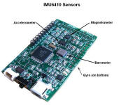
The IMU6410 is a sophisticated MEMs sensor Inertial Measurement Unit platform with ten Degrees Of Freedom (DOF), onboard AVR processor (ATmega1284P) , real time clock, external serial flash (1Mx8 or 8Mx8) and USB interface.  The IMU6410 combines a 3-Axis Accelerometer (ADXL345), 3-Axis Rate Gyro (L3G4200D), 3-Axis Magnetometer (HMC5883) and a Barometer (BMP085) on a single PCB with processor and USB interface.  All four MEMs sensors are digital with either an SPI or I2C interface.

The real time clock allows sampled data to be time stamped in real time.  The external Serial Flash allows sampled time stamped data to be stored in real time at user defined sample rates.

A turnkey real time data logging application developed using AVR Studio 4.19 is loaded into the ATmega1284P.  Complete source code for this application can be downloaded from our web site.  A rudimentary complementary filter is provided that outputs roll, pitch and yaw providing a AHRS capability.

The Accelerometer is capable of 4mG resolution over a +-16G range.   The Rate Gyro has three ranges - 250, 500 and 2000 deg/sec with a low range sensitivity of 17mdps.  The Magnetometer has eight ranges with a nominal resolution of 10mGauss.  The Barometer has an absolute accuracy of 8 meters and a resolution of 80cm.  Truly a unique combination of sensors. 

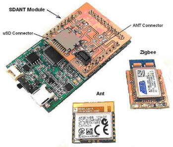
The onboard ATmega1284P processor comes with an Arduino compatible bootloader and data logging application pre-installed.  Complete source code for the data logger and bootloader are provided.  The data logger can be configure to log all sensor data to the onboard 1Mx8 serial flash or optional microSD (with SDANT daughter card)  The bootloader is stk500v2 compatible.

An optional daughter card with microSD port and ANT wireless connector is in the works and should be available shortly.

Features
    o  10 Sensors integrated on one PCB
    o  3-Axis Accelerometer ADXL345
    o  3-Axis Rate Gyro L3G4200D
    o  3-Axis Magnetometer HMC5883
    o  Barometer BMP085 with 8m accuracy and 0.8m resolution
    o  All digital sensors
    o  ATmega1284P processor with Arduino bootloader - stk500v2
    o  USB 2.0 interface
    o  Optional double AA battery holder (switch selectable with USB interface)
    o  Example application included for rapid application development
    o  1.8-3.6VDC power input 
    o  Extremely Small form factor (1.34x2.34 in)
 

Component Layout


Description
The IMU6410 is an extremely compact embedded IMU sensor platform for mobile data acquisition, instrumentation and remote monitoring applications.  The IMU6410 is an all digital implementation with no requirement for AD interfacing.   

Processor and Communication Interfaces
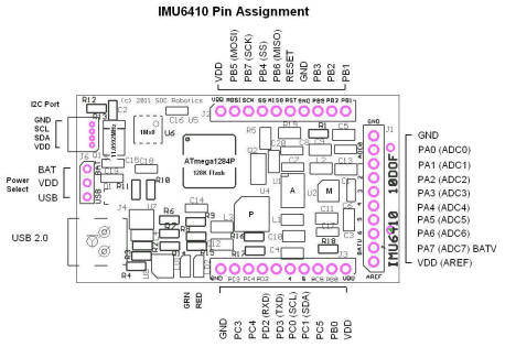
The IMU6410 uses an 8 bit AVR processor with 128K of flash - ATmega1284P.  An onboard USB 2.0 interface support high speed serial communication with the desktop.  An XR21V1410 USB serial chip with drivers for Windows, MAC and Linux allow communication with a rich set of desktops.  A real time clock crystal attached to the ATmega1284P allows real time stamping of logged data.  An onboard 1Mx8 serial flash provides limited storage for fast real time events.  The processor has two UARTs - one dedicated to the USB interface - the other available for use by other devices.  An SPI interface, 8 channel analog interface and digital IO is also available to communicate with other devices.

3-Axis Accelerometer
The 3-Axis accelerometer is an Analog Devices ADXL345.  The ADXL345 has four programmable acceleration ranges- 2G, 4G, 8G and 16G set by the ATmega644.   The ADXL345 operates from 2.2 to 3.6Vdrawing 140uA so the Wasp should not be powered higher than 3.6V when the accelerometer is installed.  The accelerometer has a sensitivity of 4mG over the full 16G range, a bandwidth of 3500Hz (XY)  150Hz (Z), non-linearity less than 1% and a cross-axis sensitivity less than 1%.

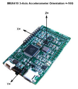
The accelerometer is oriented with the X+ on the long axis of the PCB toward Port A connector J1, Y+ on the short axis of the PCB toward Port B connector J2 and Z+ pointing up out of the board.


3-Axis Rate Gyro
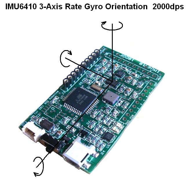
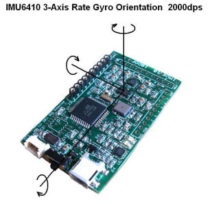
The 3-Axis Rate Gyro is an STMicroelectronics L3G4200D.  The L3G4200D has three programmable gyro ranges- 250, 500 and 200dps set by the ATmega644.   The L3G4200D operates from 2.2 to 3.6Vdrawing 6mA so the Wasp should not be powered higher than 3.6V when the accelerometer is installed.  The Gyro has a sensitivity of 17mdps (250dps setting),  a bandwidth of 350Hz (XY)  150Hz (Z), non-linearity less than 1% and a cross-axis sensitivity less than 5%.


3-Axis Magnetometer
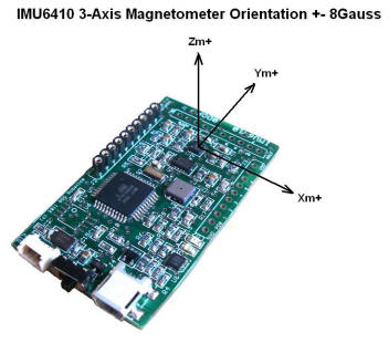
The 3-Axis Magnetometer is a Honeywell HMC5883.  The HMC5883 has eight programmable gauss ranges- 0.88G, 1.3G, 4G and 8.1G set by the ATmega644.   The HMC5883 operates from 2.2 to 3.6Vdrawing 100uA so the Wasp should not be powered higher than 3.6V when the accelerometer is installed.  The Magnetometer has a sensitivity of 2mG (1.3g setting),  a bandwidth of 350Hz (XY)  150Hz (Z), non-linearity less than 1% and a cross-axis sensitivity less than 5%.


Battery Holder
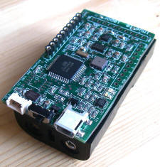
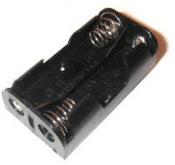
An optional double AA battery holder, attached to the bottom of the PCB, provides mobility for remote applications.  The battery holder allows inexpensive AA batteries to be used to power the platform.


Software Tools
Source code examples to setup and configure the three different MEMs sensors is provided as part of the IMU6410 Data Logger Application V0.96.  The application example is programmed in C using a Atmel's AVR Studio V4.19.  An Arduino Sketch are under development.  Check the SOC Robotics web site for program examples and the AVR Studio project file.  Note that two versions are available - V0.96 and V0.97.  V0.97 includes support for the SDANT daughter card with full FAT16/FAT32 file storage support.  V0.97 also support application bootloader support.

The IMU6410 ATmega1284P comes with an Arduino bootloader that the Arduino Development Tools can communicate with directly via the IMU6410's onboard USB port.  The bootloader implements a subset of the stk500v2 protocol and is compatible with AVRDude and AVR Studio 4/5.  The latest bootloader supports application initiation so an external jumper is no longer required.

Related Products
The following products can be used with the IMU6410:

    SDANT-IMU    microSD adapter and ANT Wireless connector for IMU6410 (available March) 


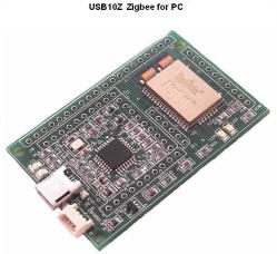
    USB10Z    Zigbee wireless with USB10 compatible USB 2.0 interface for desktop link to IMU6410.


    SmartLCD    4x12 Monochrome LCD with onboard ATmega168 and optional 3-axis Accelerometer


Downloads/Revisions
The following technical Manuals, datasheets and software downloads are available.  A new version of the data logger application specifically for the IMU6410 based on AVR Studio 4.19 is now available for download as version 0.96 or 0.97.  Version 0.97 supports the SDANT microSD and ANT/Zigbee wireless daughter card and supports application booting for bootloaders v2.01 and v2.02.   A Desktop application with Extended Kalman Filter is under development and will be posted shortly.  A version of the data logger for the Arduino environment is also under development.  The stk500v2.01 bootloader starts at 0x1E0000.  The stk500v2.02 bootloader is configure for Data Logger V0.97 and uses half the boot memory starting at 0x1F0000.  Both versions allow entry to the bootloader from the application.  If you plan to use the IMU6410 as a quadcopter controller and want to use the four hardware PWM output lines then the PCB will need a small modification. 

Technical Documentation:
     IMU6410 Technical Manual                 IMU6410 Technical Manual.pdf
     IMU6410  ATmega1284PProcessor    ATmega1284P Processor Datasheet.pdf
     IMU6410 V0.97 Release Notes              IMU6410 V0.97 Release Notes.pdf
     Modification for hardware PWM        IMU6410 Modification For PWM.pdf

Project Folders (Atmel AVR Studio 4.19 format):
      IMU6410 Data Logger  V0.96                IMU6410 Data Logger V0.96.zip
      stk500v2.01 Bootloader                           IMU6410 stk500v2.01 Bootloader.zip
      IMU6410 Data Logger  V0.97                IMU6410 Data Logger V0.97.zip
      stk500v2.02 Bootloader                           IMU6410 stk500v2.02 Bootloader.zip

Sensor Datasheets:
      ADXL345 Datasheet                                ADXL345 Datasheet.pdf
      L3G4200D Datasheet                              L3G4200D Datasheet.pdf
      HMC5883L Datasheet                             HMC5883L Datasheet.pdf
      BMP085 Datasheet                                   BMP085 Datasheet.pdf
 

Home | Products  | Download  |  Support  |  OrderingNews Contact
© Copyright 2003-2024   SOC Robotics, Inc. All rights reserved.  Privacy Policy  |  Terms of Use Disclaimers
 webmaster@soc-robotics.com  Last update:  Mar 18, 2024